• There were many reasons for the change of the site software, the biggest was security. The age of the old software also meant no server updates for certain programs. There are many benefits to the new software, one of the biggest is the mobile functionality. Ill fix up some stuff in the coming days, we'll also try to get some of the old addons back or the data imported back into the site like the garage. To create a thread or to reply with a post is basically the same as it was in the prior software. The default style of the site is light colored, but i temporarily added a darker colored style, to change you can find a link at the bottom of the site.

Pin out for that 6 pin Diagnostic connector?

Spyder Monkey

New member
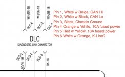
I finally got the parts to start reverse engineering the BUDS protocol and I can't seem to find the pin assignments for the 6 pin Buds connector and the service PDF is going slower than christmas for some reason. Does anybody know / have the pinout for that 6 pin connector? I think CAN Hi is White / beige and CAN Lo is White / black but I am not sure. Any help appreciated.

David
 
Progress

See the picture

Anybody explain what the "K-Line" signal is?

David
 

Attachments

  • Spyder_Diag_pinout.jpg
    Spyder_Diag_pinout.jpg
    68.7 KB · Views: 596
Last edited:
See the picture

Anybody explain what the "K-Line" signal is?

David

David, the "K-Line" is an alternative underlying physical layer for OBD via the KWP2000 protocol (ISO-9141) providing bidirectional serial communication with a data rate up 10.4 kilobaud. The CAN line (ISO-11898) is significantly faster with data rates of up to 1 Mbit/s.
 
David, the "K-Line" is an alternative underlying physical layer for OBD via the KWP2000 protocol (ISO-9141) providing bidirectional serial communication with a data rate up 10.4 kilobaud. The CAN line (ISO-11898) is significantly faster with data rates of up to 1 Mbit/s.

Thanks for clearing up the mystery. :thumbup:

I wonder if BUDS utilizes this channel, too, for some purpose.
 
David, the "K-Line" is an alternative underlying physical layer for OBD via the KWP2000 protocol (ISO-9141) providing bidirectional serial communication with a data rate up 10.4 kilobaud. The CAN line (ISO-11898) is significantly faster with data rates of up to 1 Mbit/s.


Dang it, i thought that was a double gitback. :roflblack::roflblack::roflblack:

Cruzr Joe
 
Thanks for clearing up the mystery. :thumbup:

I wonder if BUDS utilizes this channel, too, for some purpose.

Doubt it since the BUDS USB adapter is a rebadged USB to CAN adapter. But possible.

Made small progress but my CAN enabled Microcontroller had a steeper learning curve than I expected. I was able to exchange CAN messages with another microcontroller but have not yet built cable for Spyder.
 
Tried and failed at the easy path. Hooked the can lines plus the k line to an Elm327 chip to see if the dialect of can was one known to that obd decoder chip. No joy.

That Deutsch connector is an impressive little sucker. Looks very study and water tight. So now I build another cable to hook it up to my microcontroller and see if I can at least figure out the baud rate and simple messages like gear and speed.

Sent from my GT-N7000 using Tapatalk 2
 
SpyderMonkey...keep it going...all this is way-over my head...I like to put key in...start engine...ride...but Mark and lots of others could use this info to work on Spyders
 
If I was going to do this I would start by getting my hands on ISO 11898, parts 1 and 2. http://www.iso.org/iso/catalogue_detail.htm?csnumber=33422 or at least something that described it. That would give you the base data link layer and the physical signalling. Then (and this is the tricky part) you could concentrate on decoding BRP's proprietary final data layer.

Ok, at first you scared me that I was way off track but after looking at the parts, I think we agree in the approach just different ways of getting there.

CAN was developed for automotive applications but it is widely used in many industries now. Believe it or not, I learned about CAN working on building a treadmill for the ISS at NASA because the motor controller spoke CAN.

I bought http://www.embeddedartists.com/products/app/aoa_kit.php because:
  • It has CAN PHY and controller built in
  • It is cheap compared to most USB to CAN adapters
  • I already have tools and experience programming a very similar NXP microcontroller from the same family.

So I messed with it some this weekend and I got the board up and running and built the CAN example code and ran it and it works. Had some power supply headaches (turns out it really needs a full amp or you get weird errors programming the flash.

So next is to see if I can just eavesdrop on the bus and get the baud right. If that works I have to figure out how fast I can log data to the SD card (it is only accessing it in SPI mode so probably not very fast).

My company wants me to write blog posts on technical topics like this so I'll keep you guys posted of any progress.
 
Progress is being made

Not a lot of progress but some. Here is a blog post that does not cover much new ground from what is posted here that I put on my company website:
http://www.sparxeng.com/blog/hardware/reverse-engineering-the-can-am-spyder-diagnostic-interface

SpyderHacking.jpg
I built a cable that pulls 12V power from the diagnostic connector and uses a cheap DC-DC converter to step it down to 5V and then powers my AOA microcontroller setup. I ran the sample CAN code provided with the unit to talk CAN to their provided CAN node (the little tiny board on the right side) while controlling the setup from my phone. So in short, I can power my development prototype from the Spyder and communicate with another CAN device so I should be able to communicate with with the Spyder itself. Next step is to try to just passively listen to the bus and see if I can fish out simple information like gear selected.

Another blog post to follow as soon as I can get the time.

David
 
Had trouble guessing the baud rate in software so I drug the oscilloscope out to the parking lot this morning and successfully captured a CAN message off the diagnostic connector. Looks like I was guessing too low. Cool stuff, progress is being made.

Sent from my GT-N7000 using Tapatalk 2
 

Attachments

  • uploadfromtaptalk1369405905553.jpg
    uploadfromtaptalk1369405905553.jpg
    65.8 KB · Views: 87
Back
Top