IdahoMtnSpyder
Active member
About a week ago I posted this, https://www.spyderlovers.com/forums...g-up-Update!&p=1641755&viewfull=1#post1641755, explaining how the start button on my RT crapped out. Here is how I replaced it with a push button switch. I started with the right hand switch module already opened up as shown in the link. After looking at the size of the PB I decided it would fit into the RH Switch Module where the original start button was. Putting it there kept it within easy reach and meant I didn't have to open up the whole machine to get to the wiring harness!
First I popped out the starter button from the housing. It came out easily. I don't know if it was clipped or welded into place but as soon as started prying on it it popped off.
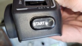
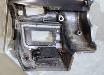
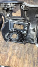
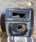
The next step was to fill in the oval hole. I took a piece of ABS pipe and cut a small piece out of it. Then I heated it with a heat gun to soften it and then flattened it with a rubber hammer. Using a coping saw and sandpaper I trimmed the piece to where it just fit into the hole. Sometime ago there was a discussion here of using acetone to soften ABS flakes to make a glue for the ABS parts on the Spyder. So I made some ABS flakes from the pipe with a saw and put them into acetone. I also dropped the patch piece into the acetone for a minute or so so its edges would be soft. I pushed the patch into the oval hole in the housing and slobbered a bunch of the ABS glue on both sides around the patch and let it set for a few hours. The outside didn't look too bad but the inside sure looked junky! I didn't care 'cause I was after function, not looks! I took the pic of the outside after I sanded it to try to make it look a bit better. A 'bit' is all I managed!
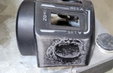
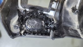
The next step was to drill a hole for the push button. It is a momentary on PB with an LED. I cut the LED leads off as I had no use for it. I used a 1/2" spade bit in a drill/driver to drill the hole. I used a Dremel to smooth out around the inside perimeter of the hole. My first attempt to drill the hole was too soon after I put the plug in. It pushed out so I had to reseat it and slobber glue on it again. That covered up the sanding I had done!
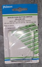
Here is the housing with the PB installed and with the switch module back in the housing as well. As you can see the PB just barely fits into the housing with the switch module in it. The PB package shows what I used. I got it at a local independent electronic parts store.
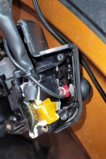
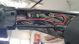
The next step was to connect the wires from the PB into the harness for the RH module. I cut the gray/beige wire to the start button and connected one of the leads from the new PB to it. I cut the black ground wire and spliced in a short piece to continue the ground to the switch module. Because space is limited in the handlebar cavity I needed to come up with a small two conductor connector. By using a connector the switch module housing can removed completely off the handlebar if there is ever a need to do that. The harness for the OEM module connects to the bike harness somewhere under the console. For connectors I used terminals from a multipin connector. Instead of crimping the wires to the terminals and inserting them into a terminal housing I used combination shrink tube/solder ring splice connectors. You shrink the tube and melt the solder with a heat gun.
Here's what it looks like now that it is finished!
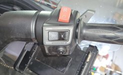
It ain't the prettiest repair in the world but it saved me from spending $500 for a whole new RH Switch Module!
First I popped out the starter button from the housing. It came out easily. I don't know if it was clipped or welded into place but as soon as started prying on it it popped off.


The next step was to fill in the oval hole. I took a piece of ABS pipe and cut a small piece out of it. Then I heated it with a heat gun to soften it and then flattened it with a rubber hammer. Using a coping saw and sandpaper I trimmed the piece to where it just fit into the hole. Sometime ago there was a discussion here of using acetone to soften ABS flakes to make a glue for the ABS parts on the Spyder. So I made some ABS flakes from the pipe with a saw and put them into acetone. I also dropped the patch piece into the acetone for a minute or so so its edges would be soft. I pushed the patch into the oval hole in the housing and slobbered a bunch of the ABS glue on both sides around the patch and let it set for a few hours. The outside didn't look too bad but the inside sure looked junky! I didn't care 'cause I was after function, not looks! I took the pic of the outside after I sanded it to try to make it look a bit better. A 'bit' is all I managed!


The next step was to drill a hole for the push button. It is a momentary on PB with an LED. I cut the LED leads off as I had no use for it. I used a 1/2" spade bit in a drill/driver to drill the hole. I used a Dremel to smooth out around the inside perimeter of the hole. My first attempt to drill the hole was too soon after I put the plug in. It pushed out so I had to reseat it and slobber glue on it again. That covered up the sanding I had done!


Here is the housing with the PB installed and with the switch module back in the housing as well. As you can see the PB just barely fits into the housing with the switch module in it. The PB package shows what I used. I got it at a local independent electronic parts store.


The next step was to connect the wires from the PB into the harness for the RH module. I cut the gray/beige wire to the start button and connected one of the leads from the new PB to it. I cut the black ground wire and spliced in a short piece to continue the ground to the switch module. Because space is limited in the handlebar cavity I needed to come up with a small two conductor connector. By using a connector the switch module housing can removed completely off the handlebar if there is ever a need to do that. The harness for the OEM module connects to the bike harness somewhere under the console. For connectors I used terminals from a multipin connector. Instead of crimping the wires to the terminals and inserting them into a terminal housing I used combination shrink tube/solder ring splice connectors. You shrink the tube and melt the solder with a heat gun.

Here's what it looks like now that it is finished!

It ain't the prettiest repair in the world but it saved me from spending $500 for a whole new RH Switch Module!
Last edited:
