DickB
Active member
Because the Ryker uses only two tail lights, a brake light flasher will display a confusing pattern when the brakes are applied with a turn signal active. For example, when braking on left turn, the left tail light is flashing and the right steady on with no brake light flasher. But, with a brake light flasher, the right tail light also flashes.
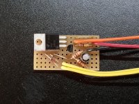
I designed and installed an override circuit that bypasses the brake light flasher when the turn signals are active.
With either turn signal on, capacitor C1 fully charges, turning on Q1 and Q2. Q2 bypasses the brake flasher module. When the turn signal flashes off, C1 gradually discharges but keeps the bypass transistor Q2 active for a few seconds - long enough to maintain the bypass until the turn signal flashes on again. When the turn signal flashing stops, C1 is fully discharged and the bypass disabled.
I used parts that I had on hand, but most any small signal diodes, NPN transistor, and p-channel FET will work.
I sealed the override module in shrink tubing and hot melt glue, wrapped it in foam, and stuffed it into a cavity behind the left tail light.