MrMagicFingers
Member
Hey Guys...
So I am doing a bunch of work to my wife’s 2010 RTS. One of the things on the list is the canisterectomy.
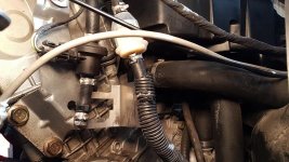
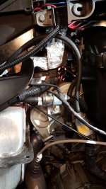
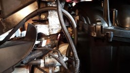
That being said, I am looking for the best spot to route the new fuel tank vent hose. I know some people route it to the front over the engine and others to the rear. The ones to the rear are either hi or low where they stop.
What does consensus say is the best spot? I am thinking rear.
I really am looking for pictures. Does anyone have any pictures of the actual route they took for the hose and where they ended? I have been searching but have not found what I am looking for.
I just got done replacing the sparkplug wires, cleaning out the air box from the most sticky oil residue I have ever come across. I was surprised at how much oil was in there. I only did this the early spring of last year before our trip!
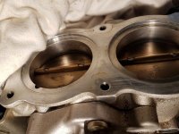
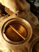
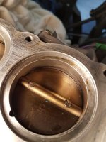
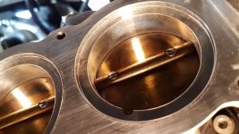
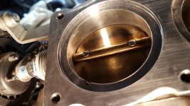
I also cleaned the throttle body. I had our first trip last year on this ruined by a limp-home code (forget the number) that said that basically the butterflies didn’t match the grip in the fly by wire system. As it turns out they were so dirty and sticky to the point they were not even closing by themselves with its own spring return. I got them all cleaned up and sparkly new and they work so much better. I am pretty sure I nabbed the problem.
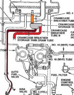
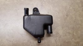
After I complete the fuel system issues, I am going to put in a catch-can type system for the crank case breather. It certainly will NOT be going back to the air box even with that fuel filter workaround!! I have a spare system from a GW1500 that I will be using for this – vented to atmosphere with a small container and a drain tube.
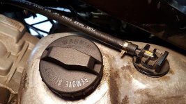
Pictures attached cause... well... everyone loves pictures. Hahaha
BajaRon – Great plug wires!!!!
Tim
So I am doing a bunch of work to my wife’s 2010 RTS. One of the things on the list is the canisterectomy.
That being said, I am looking for the best spot to route the new fuel tank vent hose. I know some people route it to the front over the engine and others to the rear. The ones to the rear are either hi or low where they stop.
What does consensus say is the best spot? I am thinking rear.
I really am looking for pictures. Does anyone have any pictures of the actual route they took for the hose and where they ended? I have been searching but have not found what I am looking for.
I just got done replacing the sparkplug wires, cleaning out the air box from the most sticky oil residue I have ever come across. I was surprised at how much oil was in there. I only did this the early spring of last year before our trip!
I also cleaned the throttle body. I had our first trip last year on this ruined by a limp-home code (forget the number) that said that basically the butterflies didn’t match the grip in the fly by wire system. As it turns out they were so dirty and sticky to the point they were not even closing by themselves with its own spring return. I got them all cleaned up and sparkly new and they work so much better. I am pretty sure I nabbed the problem.
After I complete the fuel system issues, I am going to put in a catch-can type system for the crank case breather. It certainly will NOT be going back to the air box even with that fuel filter workaround!! I have a spare system from a GW1500 that I will be using for this – vented to atmosphere with a small container and a drain tube.
Pictures attached cause... well... everyone loves pictures. Hahaha
BajaRon – Great plug wires!!!!
Tim