Flamewinger
New member
I'm installing a set of extra horns and I'm having problems with the wiring. I am connecting to the OEM horn top wire to trigger the relay with 20amp fused power. When I connect the ground wire from relay I hear the relay click. (with ignition off) When I turn ignition on the horn blasts.
Are the wires to the OEM horn + & - ?
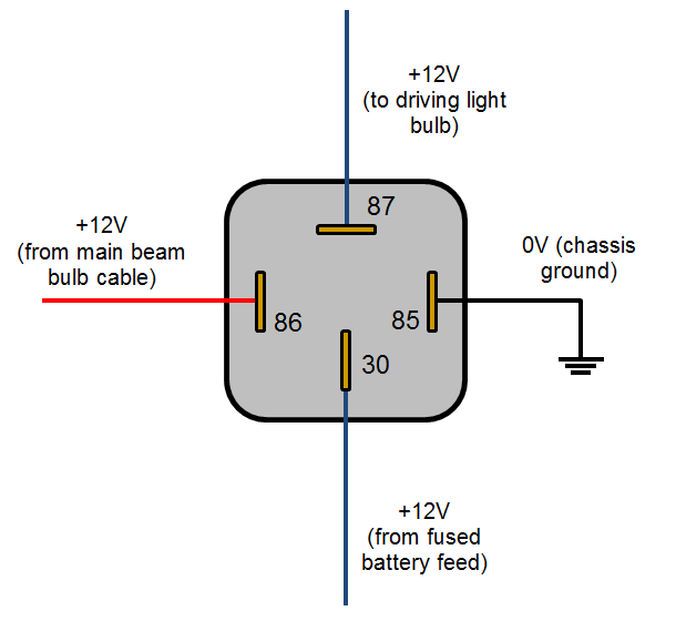
What wires go to the Relay 30 87 86 & 85 ???
Thanks
Are the wires to the OEM horn + & - ?
What wires go to the Relay 30 87 86 & 85 ???
Thanks

 pps:
pps:")