• There were many reasons for the change of the site software, the biggest was security. The age of the old software also meant no server updates for certain programs. There are many benefits to the new software, one of the biggest is the mobile functionality. Ill fix up some stuff in the coming days, we'll also try to get some of the old addons back or the data imported back into the site like the garage. To create a thread or to reply with a post is basically the same as it was in the prior software. The default style of the site is light colored, but i temporarily added a darker colored style, to change you can find a link at the bottom of the site.

Brake light wiring ?

troop

Well-known member
Hey all,
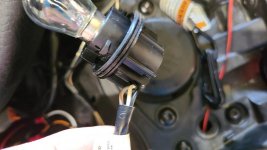
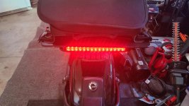
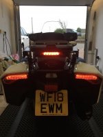
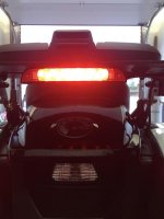
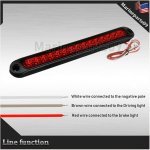
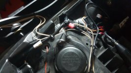
With my manual not handy, hoping someone has the answer to my brake light question? I want to posi tap my luggage rack light into my brake lights for easy disconnect. My add on light has both brake/tail light functions. Currently, I just have it wired in to the accessory wiring under the passenger seat. I'm guessing black is ground but not sure which is constant on (tail) or brake on between the solid tan wire and gray/red tracer wire. Thanks for any info..
 

Attachments

  • 20200630_131256.jpg
    20200630_131256.jpg
    40 KB · Views: 83
  • 20200627_154633.jpg
    20200627_154633.jpg
    54.3 KB · Views: 64
Best I can do right now. I do believe your signals are involved at the bulb shown in your pic. You may need to grab the brake white wire in front of the flasher or at the brake switch at the rear of brake rod. This is an uneducated guess as I have not had experience with the F3S combined tail lights.

brake flasher.jpg
 
If all you have is a single array of LEDs for supplemental brake light and want to make it a running AND brake light, you can use this simple circuit to create it.

tail-brake-LED.gif
 
SUCCESS !! Tapped a t-tap into the white wire at the brake light. All works good. Thanks :)
 
At the bulb? Have a pic? Signals don't interfere? Just trying to understand the S wiring with the dual purpose bulbs.
 
At the bulb? Have a pic? Signals don't interfere? Just trying to understand the S wiring with the dual purpose bulbs.

Here is the light. Ebay price of $11 from USA vendor. https://www.ebay.com/itm/10-inch-Se...e=STRK:MEBIDX:IT&_trksid=p2057872.m2749.l2649
Not sure if it would work as a run/brake light, I connected the ground/run wiring to my accessory connection under the passenger seat. Works good, and no big deal when on only with the machine running. For the brake light, I took the above info and t-tapped into the white wire running directly to the bulb. Running light on at start up and brake light activates when ignition on. No signal interference or hyper flash. The accessory light is quite bright and the brake light is much brighter. Not too shabby for $18 investment.
 

Attachments

  • s-l1600 (1).jpg
    s-l1600 (1).jpg
    47.3 KB · Views: 23
  • s-l1600 (2).jpg
    s-l1600 (2).jpg
    42.8 KB · Views: 25
  • 20200706_091442.jpg
    20200706_091442.jpg
    51.7 KB · Views: 29
Dunno, maybe I just don't understand the S wiring for the tail lights. Manual states that if the brake is on, you get a solid for both. But if the brake and a signal is on, you get solid on the non-signalling side and a blink on the signalling side. Which side did you grab the WHITE from the bulb?
 
Grabbed it from the left side bulb. Figured I'd leave well enough alone with the running light wires and keep attached to accessory connection. All signal lights work correctly both left and right with brake light both activated and off.
 
Thanks troop. I'm guessing I still don't get the wiring of a CANBUS. Does the rear oem turn signal blink with the fronts in sync? Meaning when the front is lit, is the back one lit or does it work inversely. Reason I ask is .... well, here's a circuit which uses the hot from one light (#2) as ground for another light (#1). If the other light #2 goes hot, light #1 loses ground and shuts off. In the 70's GM would wire their side markers this way. It used the +12v from the signal as ground. Then when the signal went flashing, each time it went hot, the marker would go dark hence it would flash inversely with the actual blinker.

ledreflectorlights.gif


Slingmods have a cubby (side vent) set of LED strips that are nice, but they are always on until you turn in your signal then they blink inversely with your actual signals. I didn't like that inverse and wanted them to blink with my signals but remain dark when not in use. You can see how I added my version of cubby lights to my SPyder at the link in my signature.
 
Unless your a Software Engineer, you really don't need to know a whole lot about CAN BUS.

https://en.wikipedia.org/wiki/CAN_bus

In short - it's a communications bus that allows microprocessors to talk to each other. Modern vehicle systems have dozens of microprocessor controlled sub-systems such as your engine ECU, your entertainment head-end unit, your ABS system, your vehicle stability system, your exterior lighting controller, and so on. They all talk to each other and operate as a complete system. CAN BUS is just the communication link between all them. Think of it as your vehicle's own private (internet) network just for its many computerized sub-systems... :yikes:
 
Back
Top