• There were many reasons for the change of the site software, the biggest was security. The age of the old software also meant no server updates for certain programs. There are many benefits to the new software, one of the biggest is the mobile functionality. Ill fix up some stuff in the coming days, we'll also try to get some of the old addons back or the data imported back into the site like the garage. To create a thread or to reply with a post is basically the same as it was in the prior software. The default style of the site is light colored, but i temporarily added a darker colored style, to change you can find a link at the bottom of the site.

Want bright LED Turn signal indicator lights - where to tap into their circuit without CANBUS yelling at me?

Columbia

Active member
The instrument panel turn signal indicators are impossible to see in the daylight. I've read that a few folks have mounted LEDs elsewhere on the bike, either on the "dashboard" or on the mirrors.
My question is where to tap into the turn signal wires. Turn signals use CANBUS to communicate, sending a message to turn the signal lights on or off as required.
I've heard again and again to not add or subtract anything from CANBUS-controlled circuits.
If I tap into the Left or Right signal wires at the back of the instrument cluster, will CANBUS yell at me? I'm planning on linking an LED to the signal wire, installing the LED in a visible location on the "dashboard" to even with bright sunlight, I can see if the turn signal is on or off. The LED draws close to zero amps/watts/whatever the correct measurement term is.
Your thoughts?
Yes: I searched. Found the very informative primer on CANBUS. Makes me think this is NOT something I can(bus) do. BUT, I sure would like to! the LED's low draw prompts my question.
Your advice/counsel is muchly appreciated.
 
I believe I saw somewhere that you could tap into the indicator wiring at the mirror itself & add a small LED repeater on the mirror body itself. Not as OEM-like as in the instrument cluster but probably a lot easier.
 
All that was needed to make mine visible in the daylight was a small shelf above the indicator lights to block direct sun from them. About a quarter inch was enough.
 
Turn signals use CANBUS to communicate, sending a message to turn the signal lights on or off as required.
I think you understand this, but your description is a bit unclear (at least it was to me on first read). The turn signal switch is on the CANBUS, and the CANBUS messages are received by the cluster. The turn signal lights are wired directly from the cluster, so the cluster is operating them. As you stated, indicator LEDs as you described draw little current as compared to the incandescent bulbs.

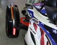
My 2014 RSS has fender LEDs installed by the previous owner. The LEDs are on with the ignition and flash brighter with the turn signals. His wiring skills were not great and the wiring is a bit of a mess, so I haven't traced exactly where he tapped, but I believe they are just wired in parallel with the turn signal lights. The turn signals did hyper-flash when I got the Spyder, I but found the way to correct that on the forum. Keep in mind that these fender lights use multiple LEDs, so they are drawing more current. Adding a single LED should cause no problem.

turn signals.png - 20251013_120302.jpg
 
Hmmm. This is all helpful. Thanks, guys.

I thought about a cluster shade, and tried that with a temporary one: card-stock and tape. My cluster might be different from yours, GWolf; the improvised shade made no difference and, with the sun behind me, the signal lights are invisible. Sun overhead, with or without the shade, they were difficult to distinguish, bordering on impossible. A good, simple solution which, unfortunately, won't work on my ST.

"Unclear"? Moi? Surely you jest! No great surprise! Sorry for that.

Let me see if I understand you, DickB:
I have yet to pull the gauge cluster to hunt for wires. When I do, I should find separate wires leading from the cluster (or a plug carrying the wires,) which serve the turn signal indicators on the cluster. Yes?

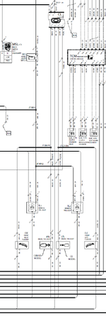
I assume, my vision not being very good at reading the circuit schematics in my manual, that the switch on the handlebar triggers the CANBUS, which triggers a relay, which then powers the turn signal light on the mirror and indicator light on the cluster - correct? (And after doing that, the CANBUS is out of the loop, except for its overall monitoring of power on the bike's circuits, with an eye out for over-current. Again: Yes?)

The CANBUS has its own wire(s), yes? So all the CANBUS business, so to speak, stays "in" the switch (and relay)? Using my limited understanding: The switch tells the CANBUS to signal the relay, which sends power to both the turn signal itself, and to the indicator in the cluster:

I easily become obtuse, complexifying things, overthinking, complicating, etc. Especially when I have deficient knowledge, e.g. about CANBUS.

The CANBUS is able to detect too much power-draw on the circuits it monitors. I know a tiny LED isn't going to present much of a power surge.
If I trace the turn signal's signal wire(s) at or near the cluster, and tap into the right and left wires, you are thinking the additional LED won't trigger a CANBUS error - yes?

I prefer not tapping into the wires at the mirror, since the LEDs will be mounted close to the cluster. Occasionally, I prefer neat and tidy, especially when wiring. If the mirror is the only place I may tap, so be it. I suspect, in all my ruminating over this, that the solution is quite simple and staring me in the face. I guess I could pull the cluster and try what I'm talking about. An error code pops up, no big deal; I'll scurry to another solution.

Again: THANKS!
 
Doesn't TricLed, or somebody, make a short LED strip that plugs into the turn signal harness and uses tape to secure to the top of the mirror, to make the turn signal easy to see??
 
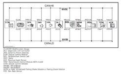
There are no relays in the turn signal system. The turn signal switch sends a CANBUS message, which the cluster electronics receive and activates the indicators in the cluster. The cluster also drives the front and rear turn signal lamps using solid-state electronics - no relays. There is no "flasher" relay as that on/off action and speed is controlled directly by the electronics in the cluster. The CANBUS is completely separate from anything else. Adding load to the turn signals will not cause a CANBUS error; nothing on the CANBUS is being touched. The only thing that may happen, as it apparently did in my case, is cause the turn signals to flash at a faster rate. The cluster probably measures current draw and does this to indicate a burnt-out incandescent bulb (I don't know this for a fact as I have not tested it). I'd be completely surprised if adding a single LED to a turn signal circuit with incandescent bulbs causes enough change in current draw for the cluster electronics to complain about anything.

On my RSS, the cluster pops out, permitting access to a pair of connectors to the mirror/front turn signals. These must be disconnected to remove the mirror/turn signal combination. This makes it super easy to identify which wires are what. One could splice in at either side of those connectors. Don't know about the ST. I've been getting ads from connectorexperts.com. A super clean and reversible installation could be done by getting a pair of connectors, if they are available, and making up a Y harness to insert inline at these connectors. But yes, you can identify the turn signal wires out of the cluster and tap in there.

CANBUS.JPG
 
See how I complicate things?!
Thanks for clarifying. I'm getting my brain wrapped around CANBUS. And I see my way forward with the indicator lights.
Multiple thanks.
 
Back
Top